
introduction:
I have been going back and forth between Modo and Maya for a number of years, and before that it was LightWave and Maya. And in all that time I have always said that Maya seems like a second language to me. I understand the philosophy behind it, most of the time, but I never have considered myself to be an expert in Maya. Well that all changed not to long ago.
I realized that even though my personal preference to create 3D assets is Modo, I am a professional, and I use Maya to make my living. So I embarked on a quest to create a project that I could do in parallel, in both Modo and and in Maya.
Welcome to The Nautilus Project. I know it may be cliché, but that is why I choose this as the place to start. . when first learning to model in a 3D package, after graduating from primitives, most people will jump to something fun, and moderately challenging, often times a spaceship. Maybe it’s the Millennium Falcon or an X-Wing, when I first started the Eagle from Space 1999 was a favorite of a lot of people. But for me, I love the Nautilus from Walt Disney’s 20,000 Leagues Beneath the Sea. So this is where I’m Starting:
Prep Work: have a plan
You could just jump in and start modeling but, I want to approach this as though this is a paying gig. So I want some reference material. There is no where better place to research the Nautilus than www.disneysub.com But really I started by just doing a google search for Nautilus Blueprints. You can see here the image that I downloaded.
I took this in to photoshop, and proceed to lay out some guides. First you will notice that the plans are divided into 10ft increments. This makes getting everything to line up much easier. So I lay out a guide on each ten foot mark, one at the tip of the nose and one at the end of the rudder. I noticed that the top and bottom portion of the images does not quite line up. it was probably a composite of two separate sheets. So after some quick rescaling, I got everything close enough. I mirrored the Front view and the Bottom view. and ended up with TOP.jpg, BOTTOM.jpg, SIDE.jpg, FRONT.jpg and SLICES.jpg all the images are 2024 long so the will line up.
DownLoad Images HERE
First Step: image Planes
modo:
- In the Item List choose Add Item, And I add two Backdrop items to the list.
- Name one BD_Top and one BD_Side... or whatever works for you.
- Select the BD_Top, and in its properties add the Top image to the image field. When you click on the Image field it will open the clips bin. at the top you will see Add Clips, select (Load Image). Then select the image after you have loaded it. (Secret Tip: You can load as many images as you want at the same time, just multi select everything you want to load into the bin. So feel free to load the top, the side, and the Slices images now.)
- I set it's Projection Type to Top, and I give it at least a 50% transparency (also I will give it a -90 Y Rotation. this will keep my model along the Z axis as we build).
- Then For the BD_Side I add the Side image. Since we added this image to the bin before just click on the Image field and select the image from the bin.
- Leave it as projection type right, and set it's transparency to at least 50%
- Now before we move on I want to work in correct scale. Since we know the divisions on the plans are 10ft,
- I make a 10ft cube as reference.
- I Could just grab the BD items and scale them but on the Back Drop Properties there is a setting for Pixel Size.
- I found that if I set this to 2.667 cm, it works perfectly .
fig 1.0
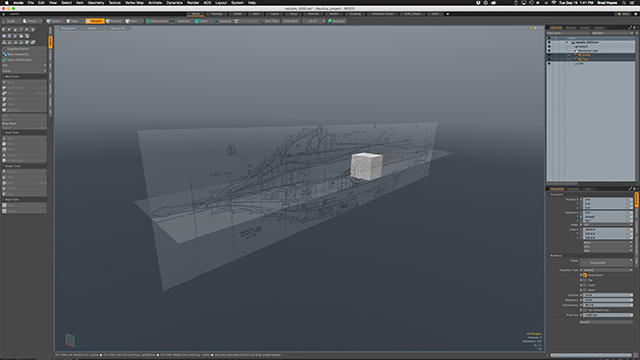
fig 1.1
Maya: Build
- First, in preferences, I set my units to feet. Then I make my 10ft cube. After, immediately set units back to centimeters.
- I made two planes: Side 2024 x 423 and Top 2024 x 338 to match the size of the images.
- Rotate the planes so they are oriented down the Z axis.
- Scale the planes so that the ten foot marks are about the same size as the cube. (This is a cheat. But since we know that in modo we used 2.667cm as the pixel size, in Maya just set the scale to 2.667 instead of 1.0.)
texture
- Open the Hypershade Windows>Rendering Editors>Hypershade, and create two lambert shaders.
- For the first shader, add a File Node to the color channel, and load the Side image.
- You should now see the image on the plane in the viewport. However the UV map will not be set to the full image.
- Go to Windows>UV Editor. You might not see the UV wireframe if the image is displayed. Click the Display Image button (fig 2.0) to turn it off. now you can see that the UV was created in the aspect of the plane. So, with the RMB Marking Menu switch to edit UV's and select the upper two points. You will probably want to turn on snapping for this. (fig 2.1)
- Hit the <w> key to move the points and drag them up so that the square covers the entire UV space.
- Now the image of the side of the sub should fill the plane and be the correct aspect.
- Repeat the entire process for top plane. Then set the transparency on both lambert shaders to at least 50%.

Fig 2.0

Fig 2.1
Finish
At this point you can freeze the transforms and delete the history for the image planes. Modify>Freeze Transforms. And Edit>Delete by Type>History. The last step I would recommend, is making the Planes into reference items.

Fig 3.0
- Select the first plane, and then go to the bottom of the channel box panel. You should see the layers editor. (fig 3.0)
- Click the Make new layer from selection button. Then do the same for the other layer.
- Now on both layers Name them, and set them to Reference.
- This will allow you easy access to turn the visibility on and off, and you can not manipulate them while modeling on top of them.
fig 3.1
You should now have the starting point for either, or both programs.